 Carter
(Simple, Single Acting, Bump Valve, Uniflow Steam Engine)
LINK TO ABOVE ARTICLE
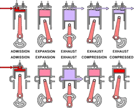
The drawing, above, illustrates counterflow operation in the top row and uniflow in the bottom.
*
The left-hand images illustrate hot (red) steam entering both engines through an inlet valve in the cylinder head.
*
The second drawings to the left depict the steam at some time after cutoff, the dimmer color indicating the
reduction of temperature and pressure accompanying expansion.
*
The middle drawings illustrate exhaust for both engines, the counterflow engine exhaust valve opens to allow the
steam to reverse direction and exit through the head. Steam exits the uniflow engine when the piston uncovers
exhaust ports arrayed in a belt around the bottom of the cylinder.
*
The second drawings to the right reveal the counterflow engine exhaust valve is still open and steam exhausts
through the cylinder head; the uniflow exhaust ports are now covered and the piston begins to compress steam
remaining in the cylinder, causing temperature and pressure to rise.
*
In the right hand drawings the piston is nearing TDC and the counterflow engine is still exhausting while the
uniflow engine has compressed the remaining steam almost to the admission pressure and temperature.
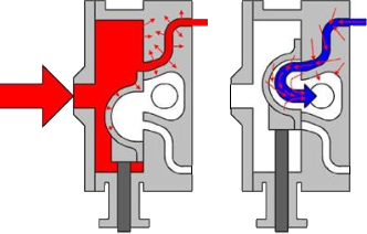
Heat distribution varies widely between D-valves, counterflow poppet valves and
uniflow engines. The drawing (right) illustrates the flow of steam through a D-valve to
and from the top end of a cylinder. In the left hand drawing hot, pressurized steam
enters the steam chest and the D-valve directs it into the top portion of the cylinder, the
small red arrows signify the flow of heat into the cooler metal walls of the valve body
and the D-valve itself. The right hand drawing shows cool exhaust departing the upper
cylinder, cold steam passing the valve body walls and D-valve pick up heat deposited by
the incoming steam and carry it out the exhaust. This heat energy never entered the
cylinder and is considered wasted.
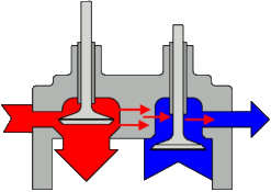
Hot, pressurized steam enters the counterflow engine (at left) through the admission valve
while cold, expanded steam departs through the exhaust valve. Though normally only one
valve would be open at any moment, for illustration both are shown as open. Heat cannot
readily migrate with the steam flow because, unlike the “D” valve, the use of separate
admission and exhaust valves and passages prevents the flow of hot steam against
surfaces that cool exhaust has already contacted. The close proximity of the valves does
allow heat to migrate through the metal in the cylinder head, which causes a loss, but the
losses are mild compared to the “D” valve.
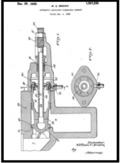
This patent drawing is assigned to the Stumpf Unaflow Engine Company of
Syracuse, NY. The valve senses when recompression exceeds supply steam
pressure and opens a passage from the cylinder head to an auxiliary clearance
volume, an additional chamber which reduces the compression ratio. The use
of auxiliary clearance permits a small clearance volume at cruise and a larger
volume for higher power needs and thus tends to improve overall economy. It
also reduces the chances of damaging an engine due to excess pressure buildup
at the top of the piston stroke.
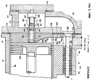
The Williams brothers patented a different approach by employing
what is basically a check valve between the cylinder head and the
steam chest. Excess compression passes from the cylinder head back
into the steam chest, preventing pressure build up, while the valve
prohibits steam flow in the opposite direction. On average, this valve
appears a bit more efficient at steam automobile temperatures and
pressures than the auxiliary clearance space, but mixing the
recompressed steam with the incoming still reduces efficiency a bit.
The Carter engine actually does something similar, the bump valve
can function as a relief valve, if compression is excessive it will lift
before making contact with the lift pin and allow the excess steam to
flow back to the steam chest.
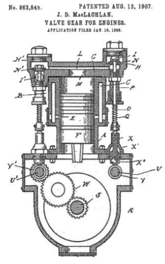
Above, yet another interesting means of minimizing clearance and preventing over-compression. The connecting rod in this double acting
engine (far right in drawing) incorporates a lever which moves a piston valve (attached to valve rod) inside the piston itself. This piston
valve exhausts steam from whichever side of the piston is currently undergoing compression, through the piston, and into the uniflow
exhaust port. This is a true uniflow, the steam is still admitted and exhausted at opposite ends of the stroke. The valve still closes before
the piston reaches the end of the stroke, permitting compression to near admission pressure to minimize the effects of the clearance
volume. Because of this closure delay, the clearance volume can be correspondingly smaller and efficiency likewise improved.
A new pair of new terms have been added to the engine definition at the top of the page, “Bump Valve” and “Uniflow”, the Carter engine
embodies both.
Carter
(Simple, Single Acting, Bump Valve, Uniflow Steam Engine)
LINK TO ABOVE ARTICLE
The drawing, above, illustrates counterflow operation in the top row and uniflow in the bottom.
*
The left-hand images illustrate hot (red) steam entering both engines through an inlet valve in the cylinder head.
*
The second drawings to the left depict the steam at some time after cutoff, the dimmer color indicating the
reduction of temperature and pressure accompanying expansion.
*
The middle drawings illustrate exhaust for both engines, the counterflow engine exhaust valve opens to allow the
steam to reverse direction and exit through the head. Steam exits the uniflow engine when the piston uncovers
exhaust ports arrayed in a belt around the bottom of the cylinder.
*
The second drawings to the right reveal the counterflow engine exhaust valve is still open and steam exhausts
through the cylinder head; the uniflow exhaust ports are now covered and the piston begins to compress steam
remaining in the cylinder, causing temperature and pressure to rise.
*
In the right hand drawings the piston is nearing TDC and the counterflow engine is still exhausting while the
uniflow engine has compressed the remaining steam almost to the admission pressure and temperature.
Heat distribution varies widely between D-valves, counterflow poppet valves and
uniflow engines. The drawing (right) illustrates the flow of steam through a D-valve to
and from the top end of a cylinder. In the left hand drawing hot, pressurized steam
enters the steam chest and the D-valve directs it into the top portion of the cylinder, the
small red arrows signify the flow of heat into the cooler metal walls of the valve body
and the D-valve itself. The right hand drawing shows cool exhaust departing the upper
cylinder, cold steam passing the valve body walls and D-valve pick up heat deposited by
the incoming steam and carry it out the exhaust. This heat energy never entered the
cylinder and is considered wasted.
Hot, pressurized steam enters the counterflow engine (at left) through the admission valve
while cold, expanded steam departs through the exhaust valve. Though normally only one
valve would be open at any moment, for illustration both are shown as open. Heat cannot
readily migrate with the steam flow because, unlike the “D” valve, the use of separate
admission and exhaust valves and passages prevents the flow of hot steam against
surfaces that cool exhaust has already contacted. The close proximity of the valves does
allow heat to migrate through the metal in the cylinder head, which causes a loss, but the
losses are mild compared to the “D” valve.
This patent drawing is assigned to the Stumpf Unaflow Engine Company of
Syracuse, NY. The valve senses when recompression exceeds supply steam
pressure and opens a passage from the cylinder head to an auxiliary clearance
volume, an additional chamber which reduces the compression ratio. The use
of auxiliary clearance permits a small clearance volume at cruise and a larger
volume for higher power needs and thus tends to improve overall economy. It
also reduces the chances of damaging an engine due to excess pressure buildup
at the top of the piston stroke.
The Williams brothers patented a different approach by employing
what is basically a check valve between the cylinder head and the
steam chest. Excess compression passes from the cylinder head back
into the steam chest, preventing pressure build up, while the valve
prohibits steam flow in the opposite direction. On average, this valve
appears a bit more efficient at steam automobile temperatures and
pressures than the auxiliary clearance space, but mixing the
recompressed steam with the incoming still reduces efficiency a bit.
The Carter engine actually does something similar, the bump valve
can function as a relief valve, if compression is excessive it will lift
before making contact with the lift pin and allow the excess steam to
flow back to the steam chest.
Above, yet another interesting means of minimizing clearance and preventing over-compression. The connecting rod in this double acting
engine (far right in drawing) incorporates a lever which moves a piston valve (attached to valve rod) inside the piston itself. This piston
valve exhausts steam from whichever side of the piston is currently undergoing compression, through the piston, and into the uniflow
exhaust port. This is a true uniflow, the steam is still admitted and exhausted at opposite ends of the stroke. The valve still closes before
the piston reaches the end of the stroke, permitting compression to near admission pressure to minimize the effects of the clearance
volume. Because of this closure delay, the clearance volume can be correspondingly smaller and efficiency likewise improved.
A new pair of new terms have been added to the engine definition at the top of the page, “Bump Valve” and “Uniflow”, the Carter engine
embodies both.
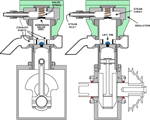
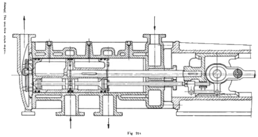


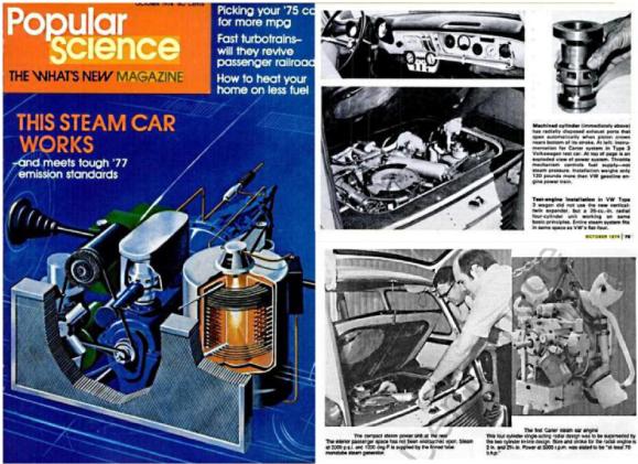
 The illustrations above approximate features in one of the cylinders in the Jay Carter Enterprises steam VW sedan conversion of
the mid-1970s. A combination of spring tension and steam chest pressure holds the admission valve disc against a seat in the
cylinder head. As the piston nears top dead center, the lift pin atop the piston forces the valve disc off the seat, allowing steam to
enter the cylinder until piston downward motion returns the disc onto the seat. Admirers of the system refer to it by what they
feel is the descriptive term ‘bump valve’ while detractors use ‘bash valve’ for similar reasons. Bump valves are inherently short
cutoff device because the valve is opened for an equal period before and after TDC. At short cutoff, inertia can carry the piston
past TDC even though the valve is open; long cutoff allows too much steam to enter the cylinder and brings the engine to a halt.
As you can see in the drawing below, the spring is surrounded by the incoming steam. These temperatures cause normal springs
to lose their “springiness”, special superalloy springs are needed to ensure correct operation.
We have only discussed counterflow engines, engines having cylinders that admit and exhaust steam from the same end, the name reflecting
that the steam must flow down the cylinder in one direction during expansion and flow in the counter direction during exhaust. Uniflow
engines place the admission and exhaust at opposite ends of the cylinder, the steam having a flow in one direction from admission to exhaust.
The alternate heating and cooling of D-valve (and similar piston valve) passages causes heat to flow from the inlet to outlet port without
performing useful work in the cylinder. Separate admission and exhaust valves significantly reduce these losses while uniflow engines even
minimize the heat flow along the length of the cylinder wall.
Uniflow engine compression and clearance volume are closely linked. Minimum clearance volume theoretically improves efficiency, but too little
clearance volume can cause the engine to recompress remnant steam above the admission pressure, degrading both efficiency and performance.
The calculations become more difficult when we consider that the exhaust pressure determines the recompression pressure for a given engine, and
the exhaust pressure can vary significantly due to changes in engine load, vehicle speed, and ambient temperature and so on. The usual solution is
to design for best efficiency at cruising speed on a ‘typical’ day, leaving in some leeway to allow the engine to still operate reasonably well
under other conditions. There have been engines that adopt a more flexible approach:
Another tried-tried and true method of dealing with compression is the
auxiliary exhaust valve (commonly, aux exhaust). In the engine to left, there
are two valves. Since compression steam attempts to lift the valve to the right
open, it is obviously the steam admission valve. The cylinder compression
presses the left valve closed, indicating it to be an exhaust valve, and an
auxiliary exhaust valve at that since the exhaust ports in the middle of the
cylinder show the engine to be a uniflow.
The illustrations above approximate features in one of the cylinders in the Jay Carter Enterprises steam VW sedan conversion of
the mid-1970s. A combination of spring tension and steam chest pressure holds the admission valve disc against a seat in the
cylinder head. As the piston nears top dead center, the lift pin atop the piston forces the valve disc off the seat, allowing steam to
enter the cylinder until piston downward motion returns the disc onto the seat. Admirers of the system refer to it by what they
feel is the descriptive term ‘bump valve’ while detractors use ‘bash valve’ for similar reasons. Bump valves are inherently short
cutoff device because the valve is opened for an equal period before and after TDC. At short cutoff, inertia can carry the piston
past TDC even though the valve is open; long cutoff allows too much steam to enter the cylinder and brings the engine to a halt.
As you can see in the drawing below, the spring is surrounded by the incoming steam. These temperatures cause normal springs
to lose their “springiness”, special superalloy springs are needed to ensure correct operation.
We have only discussed counterflow engines, engines having cylinders that admit and exhaust steam from the same end, the name reflecting
that the steam must flow down the cylinder in one direction during expansion and flow in the counter direction during exhaust. Uniflow
engines place the admission and exhaust at opposite ends of the cylinder, the steam having a flow in one direction from admission to exhaust.
The alternate heating and cooling of D-valve (and similar piston valve) passages causes heat to flow from the inlet to outlet port without
performing useful work in the cylinder. Separate admission and exhaust valves significantly reduce these losses while uniflow engines even
minimize the heat flow along the length of the cylinder wall.
Uniflow engine compression and clearance volume are closely linked. Minimum clearance volume theoretically improves efficiency, but too little
clearance volume can cause the engine to recompress remnant steam above the admission pressure, degrading both efficiency and performance.
The calculations become more difficult when we consider that the exhaust pressure determines the recompression pressure for a given engine, and
the exhaust pressure can vary significantly due to changes in engine load, vehicle speed, and ambient temperature and so on. The usual solution is
to design for best efficiency at cruising speed on a ‘typical’ day, leaving in some leeway to allow the engine to still operate reasonably well
under other conditions. There have been engines that adopt a more flexible approach:
Another tried-tried and true method of dealing with compression is the
auxiliary exhaust valve (commonly, aux exhaust). In the engine to left, there
are two valves. Since compression steam attempts to lift the valve to the right
open, it is obviously the steam admission valve. The cylinder compression
presses the left valve closed, indicating it to be an exhaust valve, and an
auxiliary exhaust valve at that since the exhaust ports in the middle of the
cylinder show the engine to be a uniflow.